he starts off by stating he don't know nothin
true to form he does, at his own admission, lump all forms together. That is not permissible.
Capacitor
Discharge
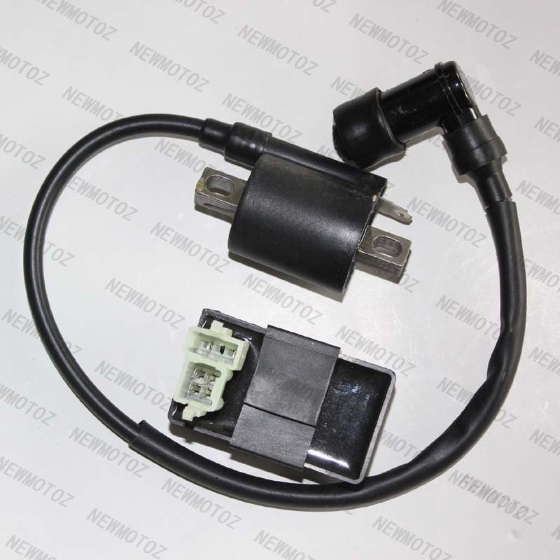
Ignitions in motorcycles do not use the battery nor do they have coils in the same sense. I was hard put to find a decent shot of one. Most of the pictures on google show everything BUT the right coil. This is one:

forget the black box
You see the coil has only one lead in and one out to the plug. The iron core is grounded as always and the lead in is plus. Already high voltage coming from the capacitor that has discharged, it is stepped some more. The CDI (
which we do not have) is not just a switch, it is a voltage storage and amplifier, the actual spark current being switched by a thyristor (used to be at least) which is controlled by the CPU. Juice is taken directly from the flywheel coil, usually a dedicated ignition coil (
the source coil in the article) separate from the lighting (if any).
They are very similar to magnetos in the way they work.
Basically all CDIs work like this and altho everyone calls the black box a CDI, most in fact are not and one should get in the habit of using the correct term.
The XTZ generator has no source coil at all:

- Screen shot 2012-04-08 at 11.21.08 AM.jpg (35.55 KiB) Viewed 7473 times
Battery ignitions work differently. At the lowest level, a breaker point which is normally closed is opened by a cam driven by the camshaft, interrupting the ground lead to the coil. This is a true transformer with two low voltage input- and a high voltage output leads. I was even harder put to find our coil with Google; lots of car coils, more CDI coils (wrong again) and lots of pencil coils.

- Screen shot 2012-04-08 at 10.51.33 AM.jpg (11.06 KiB) Viewed 7473 times
BTW, pencil coils are coils and typically have 3 spade connectors: +12 (or 24), ground and the switched ground from the black box.
Two spade connectors, plus 12v from the battery (ignition switch or relay) and ground from the black box. This true coil transforms the 12v primary to more like 30000v. not quite that simple but basically, very basically.
The black box, correctly called a
Transistor
Controlled
Ignition, opens the breaker point as it were, the CPU calculating the correct advance timing as designed, static advance is given by the position of the pickup itself, in our case at 3ºBTDC, getting this information from the number and type of noses on the flywheel. These noses are not magnets (incorrect in the article), any piece of iron will do. The SH rotor is a sheetmetal stamping:

- my racer
5 noses at 12, 1, 3, 6, 9 the 1 o'clock nose signaling once around and TDC (top dead center), the 9 o'clock nose is the actual trigger. SH's tripleSpark needs 5 noses, the XTZ has only four of which the long 11-12 o'clock signals once around. One could mill down the top long one to the same size as the other three and then add the fifth to make a SH TripleSpark work. I think the Ignitech is the better way to go here.
Here is a much better basic article on ignition systems that gets things right:
http://www.jetav8r.com/Vision/Ignition/CDI.html